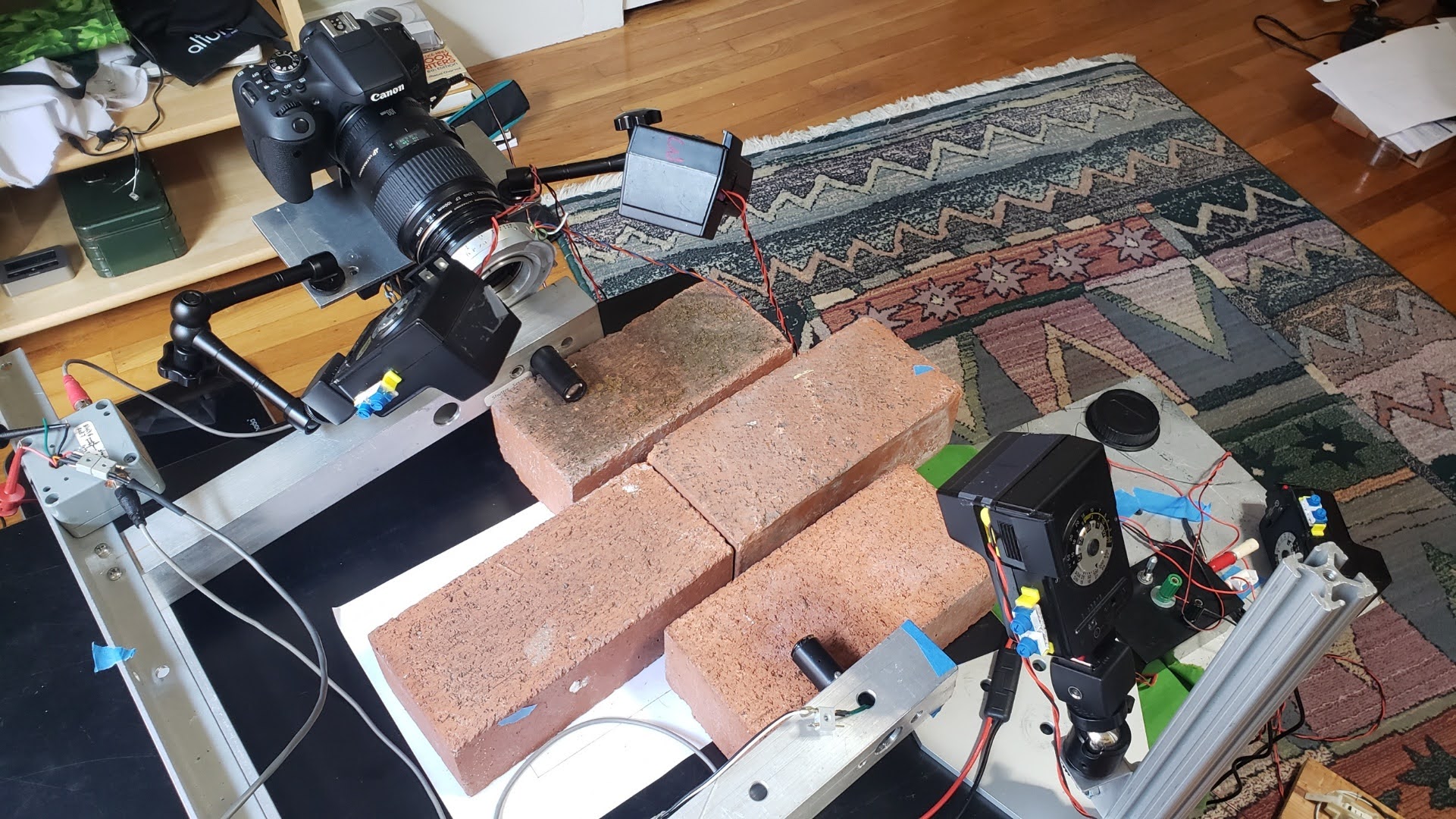
How I Work
In a nutshell, I stage a small diorama with a platform from which the spider can jump, and another platform to which it can jump. Then, I arrange a suitable background. I shine a parallel beam of light between the two platforms. If the spider jumps into the beam of light, it will trigger both the camera shutter and the flashes. Then, I focus the camera where I think the spider will be when the shutter is triggered. Finally, I introduce the spider onto the jumping platform, and wait for it to jump. Believe me, it’s not always easy! Some spiders are very cooperative. I place them on the platform and they eagerly jump over and over again. Others will jump, but always in the wrong direction, and still others are not motivated to jump at all and instead walk away, or just sit there. It takes a lot of patience on my part and often many hours to get a good photo.
Read on for more details of the system. Please contact me if you have any comments or questions.
The Light Beam and Sensor
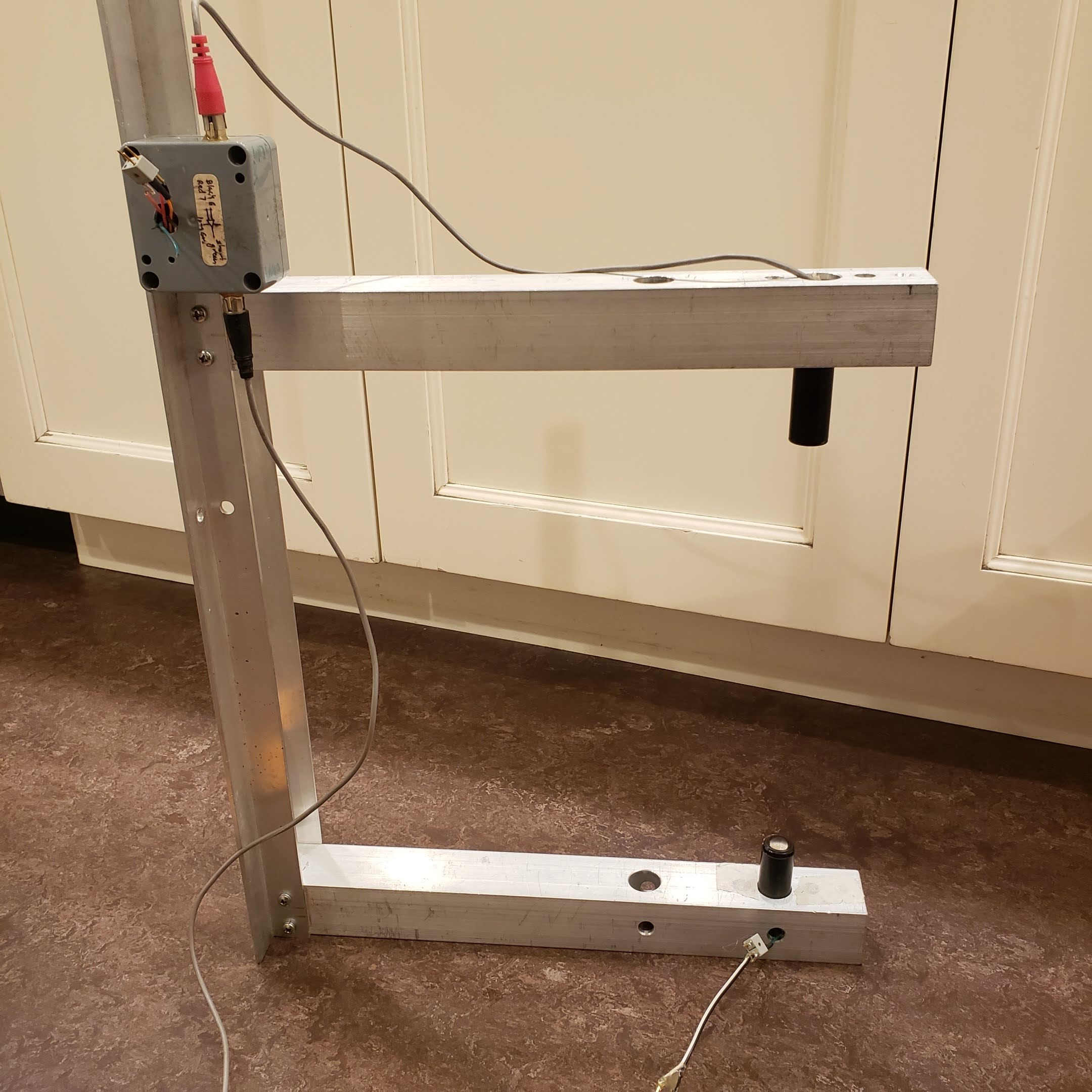
The light source I use is a tiny xenon incandescent bulb that is made for Mini Mag-light flashlights. These were once the standard for small, bright flashlights, but they’ve been replaced by LEDs. The xenon bulbs are perfect for this application, because the light source is very tiny, and thus can be focused by a convex lens into a nearly parallel beam. The lamp sits inside of a plastic tube, with the lens on the end, and I make the beam that is about 1 cm in diameter.
The beam then passes across the gap in which the spider will jump, to another, identical, convex lens on a tube. The lens focuses the light onto the tiny sensor of a phototransistor. If any object passes into the light beam, the amount of light striking the phototransistor is reduced and the transistor’s electric current decreases. Both the sensor and the lamp are held in an aluminum frame, which keeps them aligned to each other. The frame can be oriented so the light beam is vertical or horizontal. I find that I use vertical most of the time.
The Sensor Electronics
The small change in current in the phototransistor causes a small increase in voltage in the transistor circuit. For example, if I pass a piece of sewing thread through the beam, the voltage may change by 10 millivolts (1/100 of a volt). That small change is amplified by a device called a comparator, into a 5 volt increase and that 5V signal is fed into an Arduino microprocessor (a small computer). Upon receiving this 5V signal, the Arduino program commands the Arduino to trigger the camera shutter and a flash.
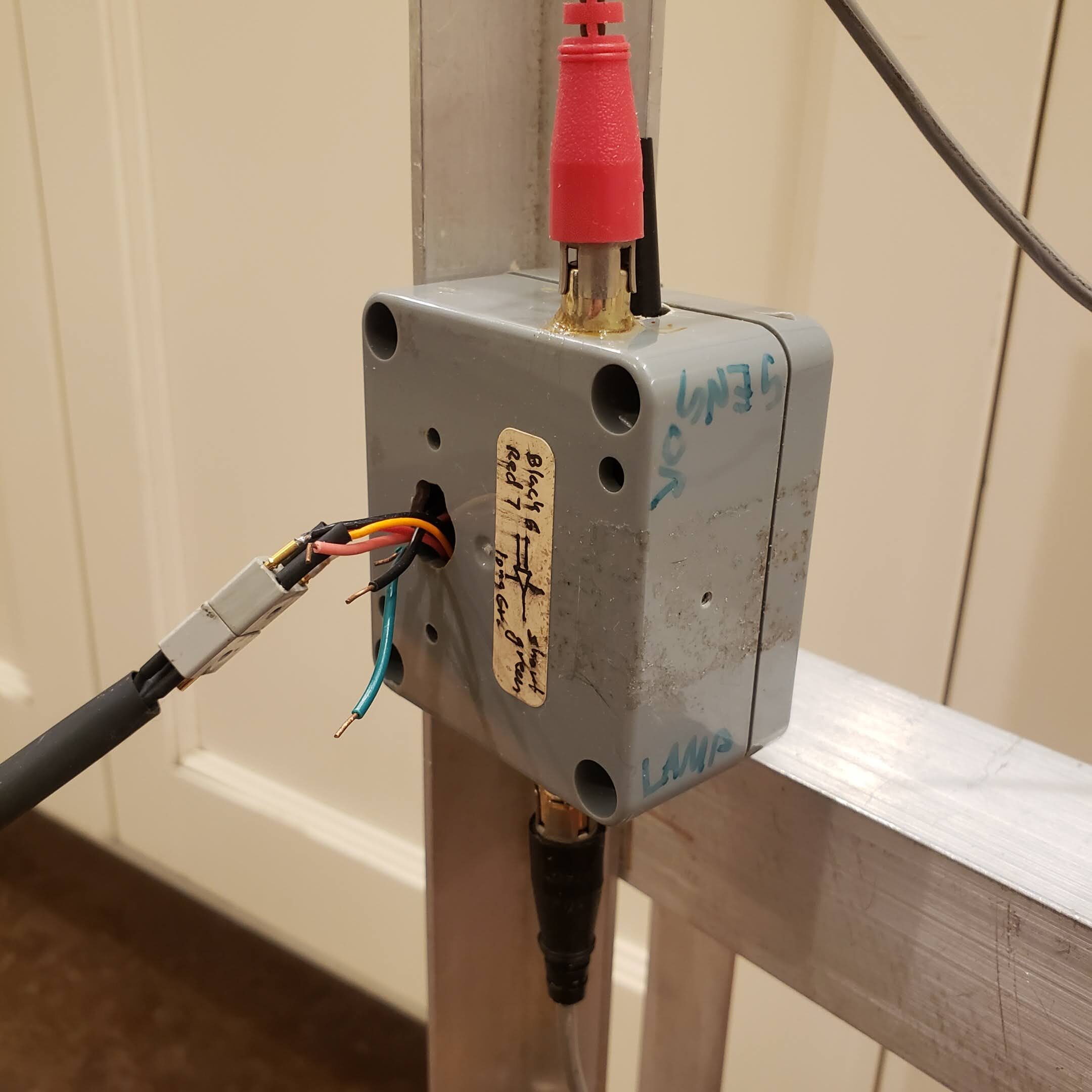
Here you can see the sensor electronics box, with the sensor wires at the top, the lamp wires at the bottom, and the wires to and from the main electronics box coming out of the center. One of these wires transmits a 5V pulse to the Arduino when the spider jumps through the beam of light.
Main Electronics Box (Control Electronics)
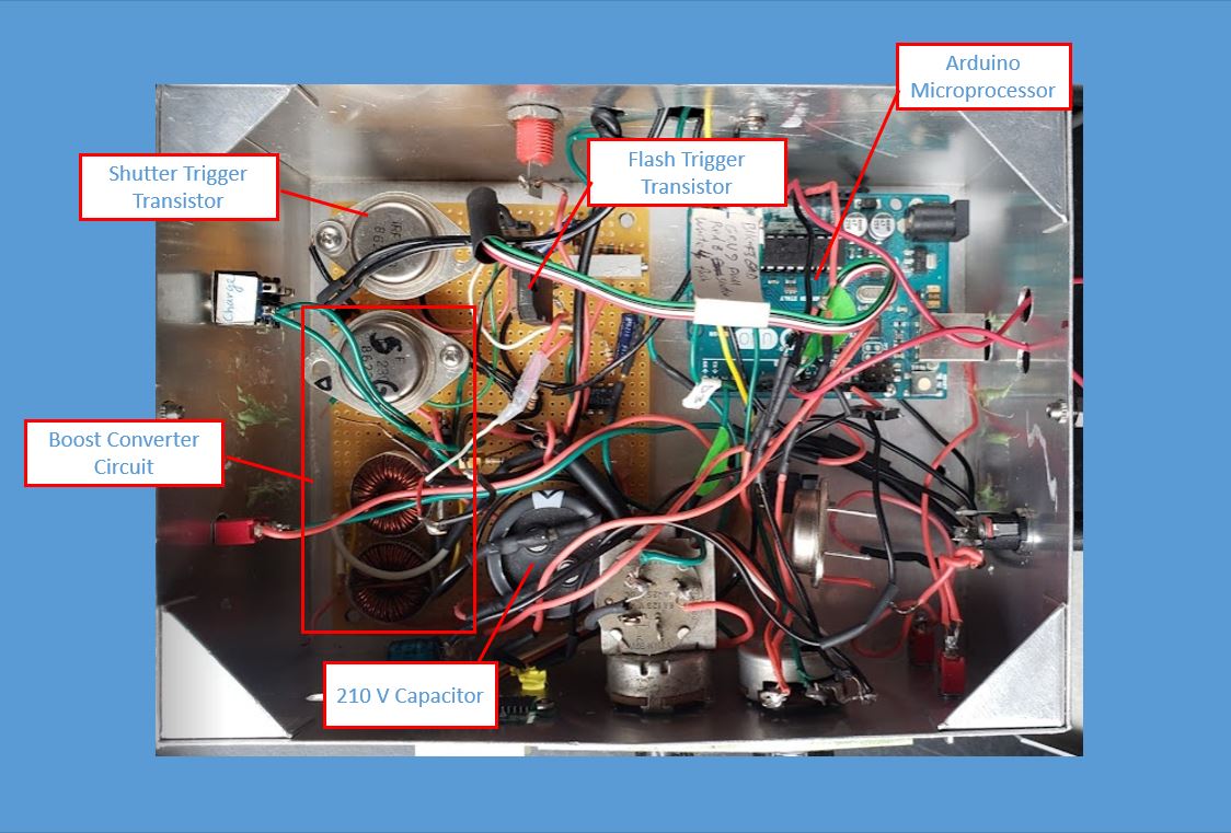
Upon receiving the 5V signal, the Arduino program commands the Arduino to trigger the camera shutter and a flash, each with a separate MOSFET transistor (a type of solid state switch). The shutter is powered by a capacitor charged to 210V. That high voltage is achieved with a circuit called a “boost converter”. A single flash is triggered and that flash in turn triggers the other flashes via optical slaves.
The Shutter
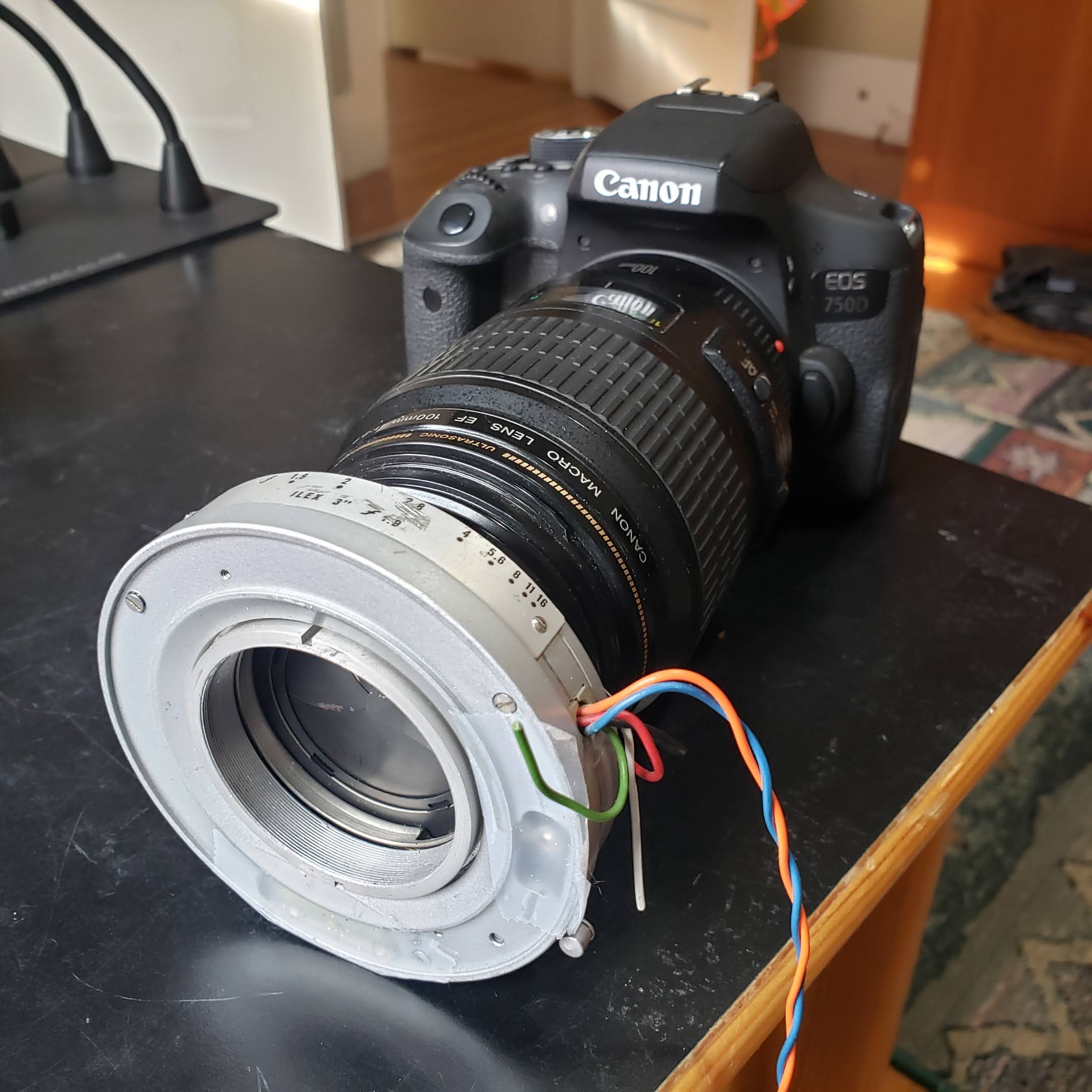
The shutter of a digital camera opens too slowly to capture the jump of a spider. If the microprocessor triggered this shutter, by the time it opened the spider would have landed already. Instead, I hold that shutter open and the spider’s motion triggers a second shutter that’s mounted on the front of the lens. Mechanical leaf shutters, which were common in cameras until the 1960s, open much more quickly. The shutter I use is an Ilex Synchro No. 3 electronic leaf shutter, which I purchased on eBay (they aren’t made anymore). The leaves of the shutter are opened by a solenoid. I apply more than 200 volts to the solenoid and the shutter opens in 10 milliseconds (1/100 second).
The Flash
A flash is an absolute necessity for freezing the motion of the jumping spider. Say the spider is 0.5 cm long and is moving at 50 cm per second, which seems typical. In order to not appear blurry in the photo, I would like the spider to move less than 1/100 of it’s body length during the photo, which means less than 0.005 cm, or 1/20 mm. Given the speed of the spider, it will take 1/10,000 of a second to move that distance. That is a minimum. In practice, I try to take my photos with a flash duration of 1/20,000 to 1/30,000 of a second, to make the images as crisp as possible. I can tell if the duration is short enough if small details, such as the spines on the spider’s legs, are sharp.
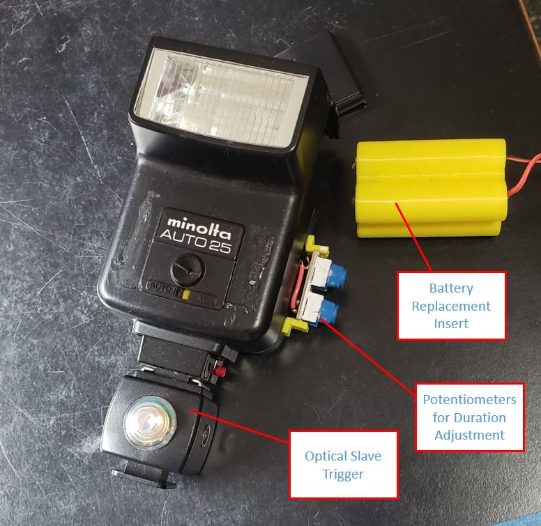
After experimenting with a number of old auto flashes from the 1970s and 80s, I found that the Minolta Auto 25 has the highest intrinsic light intensity. Using this flash, I can take photos at f/16 or f/22 at 1/30,000 sec. Before modern through-the-lens (TTL) flash metering, auto flashes used a photoresistor light sensor in the flash to measure the light reflected back from the subject. Once the intensity reached a certain level, the flash would immediately shut off. By replacing the photoresistor with a potentiometer, I can control the duration of the flash. The lower the resistance, the shorter the flash duration.
Instead of powering the flashes with the normal four AA batteries, I power them with 6V power supplies. Batteries can get expensive and, as they lose their charge the light intensity diminishes, whereas the voltage from the power supply is consistent. I introduce the power into the flash via a 3D printed part that has the same form factor as 4 AA cells.
When photographing, I typically use two flashes on the background, and two or three on the spider. Each of these flashes is connected to an optical slave trigger and they fire simultaneously about ten microseconds after the flash from the electronics box.

